Highway Guardrail Post Types: H, Sigma, U, C and Round Posts
A practical guide to identifying guardrail post profiles and checking their connection, spacer, coating and foundation requirements before procurement, installation or repair.
1. What Does a Guardrail Post Do?
A steel guardrail is a connected assembly, not simply a row of rail panels. The post supports the rail line and connects it to the ground, footing or structure through the arrangement shown in the project drawing. A change in post profile, connection location, spacer arrangement or embedment can change how the complete assembly fits together.
That is why the correct starting point is not “Which post is strongest?” The practical question is: which post is specified for this approved barrier layout and site condition? For a repair, first identify the installed system and inspect the adjacent rail, spacer, post and ground condition before ordering a replacement.
2. Quick Comparison of Common Post Profiles
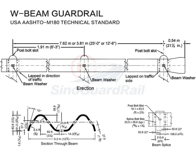
| Post type | How to identify it | What must be checked | Related page |
|---|---|---|---|
| H post | An H-shaped structural section. | Rail connection, spacer detail, holes, length or embedment and finish. | H Post |
| Sigma post | A rolled profile with a sigma-like cross-section. | Exact section, punching, layout spacing and matching connection assembly. | Sigma Post |
| U post | An open U-channel profile. | Channel dimensions, orientation, connection holes and approved spacer. | U Post |
| C post | A channel-shaped C section. | Section orientation, rail/spacer detail and footing or embedment requirement. | C Post |
| Round post | A circular steel tube or pipe section. | Outside diameter, wall requirement, connection plate or spacer, and anchoring detail. | Round Post |
3. H Posts and Sigma Posts: Confirm the Drawing Before Comparing
H post
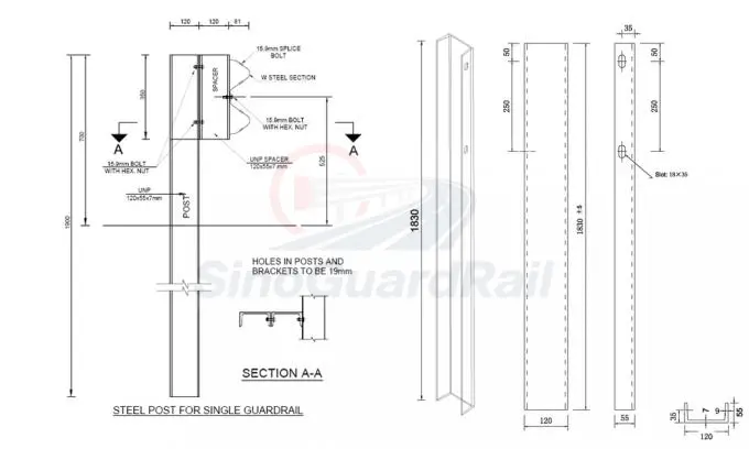
An H post is recognized by its H-shaped section. In a quotation or repair request, provide the approved profile drawing, the required hole locations, rail-to-post detail and the foundation or embedment information. A visually similar H section may have different connection details.
Sigma post
A Sigma post uses a formed sigma-like profile. Catalogued supply options include galvanized and coated finishes, while the exact material, section, punching and length must be confirmed against the project drawing. Do not use a Sigma post as a direct substitute for another profile without system approval.
4. U, C and Round Posts: Connection Details Matter
U and C posts are open channel profiles; round posts use a tubular profile. Their shape is easy to recognize, but the system cannot be confirmed from shape alone. The rail may connect through a spacer, plate, bracket or other approved component, and that connection governs the hole positions and hardware set.
-
U post: confirm which face of the channel receives the connection, the orientation in the layout and the associated spacer or blockout.
-
C post: confirm the channel section and its direction, then match it to the specific rail and post-connection detail.
-
Round post: confirm tube dimensions, wall requirement, connection plate or spacer and any required anchoring arrangement.
-
All three: provide the approved finish and site condition; do not rely on a product photo or an approximate external measurement.
5. The Spacer or Blockout Must Be Checked with the Post
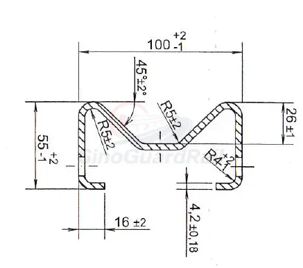
A spacer, blockout or offset block sits between the rail and the post where required by the approved assembly. It is therefore a matching component, not a general accessory. Its shape and fastening arrangement should be checked together with the selected post and rail.
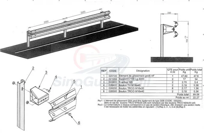
6. Terminals and Transitions Need Their Own Post Schedule
A standard line-post detail may not apply at a terminal, bridge end, transition or another change in barrier type. These locations can require a different post arrangement, rail connection, anchorage or ground detail. For this reason, terminals and transitions should be quoted and checked as complete assemblies rather than as isolated rail or post items.
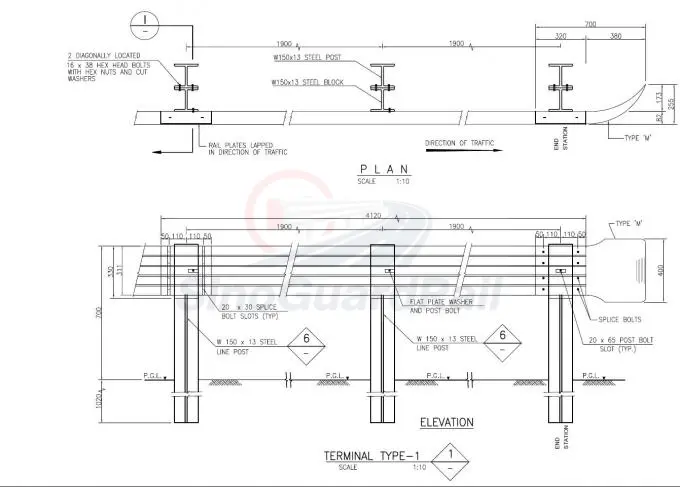
7. Post Selection Checklist for Procurement and Repair
-
Identify the full barrier system: W-beam, thrie-beam, terminal, transition, bridge interface or another approved configuration.
-
Attach the approved drawing: include the post schedule and assembly or cross-section detail.
-
Specify the post exactly: profile, material requirement, punching, finish, required quantity and any identification marking.
-
Confirm the ground connection: provide the required embedment, base plate, anchor arrangement or foundation detail stated by the design.
-
List matching components: spacer, rail, bolts, nuts, washers, plates and terminal or transition parts must be compatible with the selected assembly.
-
For repairs, inspect beyond the damaged post: check adjacent rails, splices, spacers and the surrounding ground before confirming the replacement scope.
Need Help Matching Guardrail Posts to Your Drawing?
Send the approved drawing, post schedule, rail type, spacer detail, finish requirement, quantity and destination. We can help organize matching post and hardware options for project review.
Send a Post Enquiry