A guardrail crew should not begin with a guessed post spacing or a familiar installation detail from another project. Begin with the approved system drawing. It controls the rail profile, post section, spacing, embedment or foundation, mounting height, blockout, fasteners, terminals and transitions.
This guide explains a practical installation sequence for W-beam and Thrie-beam guardrails. It does not replace the road authority specification, traffic-control plan, manufacturer's instructions or site-specific engineering approval.
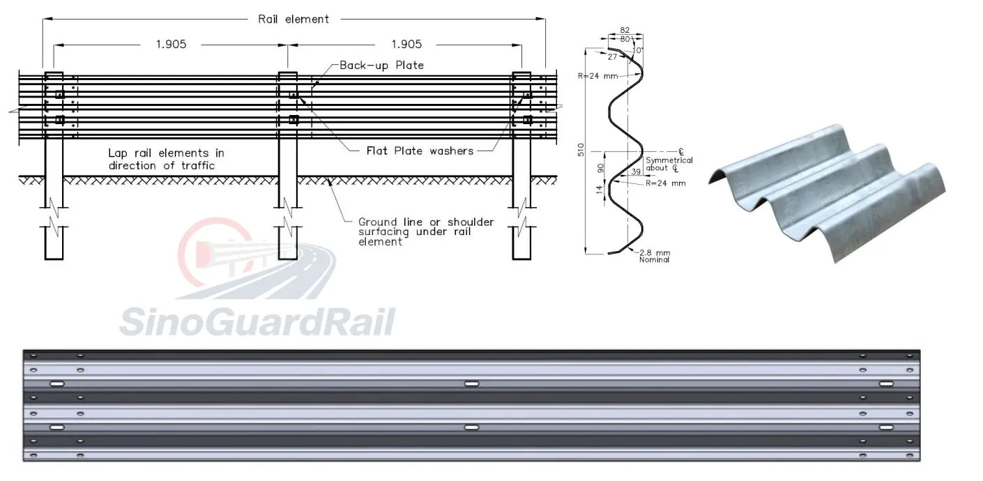
Post spacing, embedment, rail height, lap orientation and bolt torque vary by system. Mark these values on the crew's approved drawing before work starts. If the BOQ, drawing and delivered components disagree, stop and obtain written clarification.
Keep the latest approved drawings at the work front, not only in the site office. The installation team should be able to identify where the barrier run starts and ends, where the system changes, and which detail applies at every terminal, bridge approach and connection to a rigid barrier.
Sort the delivery by barrier section before distributing material along the road. W-beam and Thrie-beam rails, posts, blockouts, bolts, terminals and transition parts can look similar when bundled, but their holes and connection details may not be interchangeable.
| Check | What the Crew Should Confirm |
|---|---|
| Rails | Profile, length, hole pattern, marking, visible damage and coating condition |
| Posts and blockouts | Section, length, orientation, holes and quantity for the specified system |
| Fasteners | Bolt type, length, head, nut and washer arrangement shown in the detail |
| Special assemblies | Terminals, anchors, transitions and any nested or reinforced rail sections |
Use the guardrail post and guardrail accessories pages to identify the component groups, then verify every item against the project BOQ.
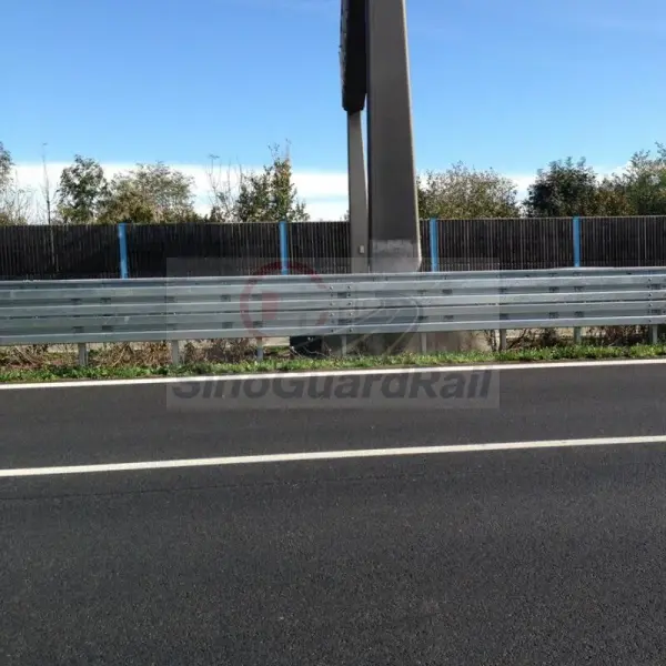
Establish the control line and reference level from the approved survey information. Mark every post position and every change in the barrier run. Identify drainage structures, buried utilities, rock, soft ground, slopes, kerbs and other obstructions before driving or excavating for posts.
Do not move a post, shorten an installation or alter the spacing simply to avoid an obstruction. Record the conflict and obtain an approved detail. Changes made at this stage can affect rail splices, terminal length and transition geometry further along the run.
Drive, set or anchor each post using the method specified for the project. Check position, orientation, line, level and exposed height before attaching the rail. Where concrete foundations or base plates are specified, confirm foundation dimensions, reinforcement, bolt position and required curing or strength acceptance before loading the connection.
Install the specified blockout or spacer in the correct orientation. Lift the rails without dragging their galvanized surfaces across the ground. Align the splice holes without flame cutting, uncontrolled drilling or forcing mismatched components together.
Follow the drawing for rail overlap and traffic-facing orientation. Fit the correct splice and post bolts, washers and nuts, but do not apply a generic torque value from another system. Tightening sequence and final torque must follow the approved detail or manufacturer's installation instructions.
A terminal or transition is not an ordinary rail splice. Set out its full length before installing it and keep its parts together as one assembly. Verify the anchor, post sequence, special brackets, connector pieces, nested rails and connection to the adjoining barrier or structure against the dedicated drawing.
Do not substitute a decorative end piece for a performance-rated terminal, or improvise a W-beam-to-Thrie-beam connection. The acceptable solution is the one specified and approved for that location.
The general workflow is similar, but the two profiles may use different hole patterns, blockouts, post connections and transition parts. Confirm the delivered rail against the relevant system drawing before installation. The fact that a Thrie-beam has three corrugations does not authorize it as a substitute for a W-beam system or establish a containment level by itself.
For profile and procurement differences, see W-Beam vs Thrie-Beam Guardrail. Available product configurations are listed under W-beam guardrails and Thrie-beam guardrails.
Walk the complete barrier run with the approved drawings. Record measurements at the frequency required by the inspection plan and close every nonconformance before handover.
| Error | Corrective Approach |
|---|---|
| Using a familiar spacing without checking the drawing | Mark the specified spacing on the approved setting-out plan |
| Forcing mismatched holes together | Quarantine the parts and verify the rail, post and blockout drawings |
| Changing a post position to avoid an obstruction | Raise a site query and install only the approved alternative detail |
| Treating a terminal or transition as an ordinary splice | Use the complete specified assembly and its installation drawing |
| Accepting a visually straight rail without measurements | Measure and record the required geometry and connection checks |
Provide the owner with approved as-built drawings, material and coating records, installation inspection forms, photographs, nonconformance close-out records and the applicable maintenance instructions. Inspection frequency and post-impact actions should be set by the road authority, asset owner and system documentation rather than by a universal website schedule.
Continue with the separate Highway Guardrail Maintenance and Repair Guide for routine inspections, corrosion observations and post-impact assessment.
Use the spacing shown for the approved barrier system. There is no single spacing that can be applied to every W-beam or Thrie-beam installation.
Measure from the reference surface and to the point defined in the project detail. Both the value and the measurement method must come from the approved drawing or system instructions.
Do not modify a safety barrier component without an approved procedure. First check whether the wrong rail, post, blockout or transition part has been delivered or installed.
Use the transition assembly specified in the approved design. A simple improvised overlap is not a substitute for a compatible transition.
Send the standard and revision, approved drawings, BOQ, material and coating requirements, inspection documents, quantities, destination and requested delivery schedule.
Send the approved drawings and BOQ so the rails, posts, blockouts, fasteners, terminals, transitions and packing can be checked before production.
Send Project DocumentsContact: Mr.Zhang
Phone: +86 13306356181
Email: [email protected]
Add: Guanxian Economic Development Zone, Liaocheng City, Shandong Province, China
We chat